Follow 


Explore our industrial-grade dielectric components, precision ceramics, and specialized material solutions manufactured to strict ISO and global export compliance standards.
Understanding dielectric breakdown voltage expansion, equivalent series resistance (ESR) accumulation, and dynamic voltage distribution in multi-capacitor series networks.
When electrical circuits require working voltage thresholds that exceed the breakdown limit of a single capacitor cell, placing capacitors in series is the industry-standard architectural solution. However, connecting capacitive elements end-to-end fundamental changes equivalent capacitance, energy storage density, and overall impedance.
As derived from basic electrostatics, the net equivalent capacitance of a series stack is always strictly less than the smallest individual capacitor in the array. Conversely, the cumulative voltage rating increases linearly—assuming perfect voltage symmetry across every dielectric barrier.
In real-world power electronics, individual capacitor cells possess inherent manufacturing tolerances (typically $\pm 5\%$ to $\pm 20\%$) and distinct insulation resistance ($R_{ins}$). Under direct current (DC) operation, the steady-state voltage across each cell is governed by its leakage current rather than its nominal capacitance value:
If a smaller capacitance cell ($C_k$) is paired in series with larger cells, it experiences a disproportionately higher share of transient overvoltage. Over prolonged duty cycles, this concentration of dielectric stress triggers thermal runaway, partial discharge (PD) inception, and catastrophic insulation puncture.
This comparative overview highlights key engineering trade-offs faced by system integrators when specifying high-voltage capacitor arrays for industrial power conversion.
| Design Parameter | Capacitors in Series Configuration | Capacitors in Parallel Configuration | Engineering Implication |
|---|---|---|---|
| Total Voltage Handling | Increases ($V_{total} = \sum V_i$) | Limited to lowest single cell ($V_{max} = V_{cell}$) | Series configuration enables HVDC and high-impulse duty. |
| Total Capacitance ($C_{eq}$) | Decreases ($C_{eq} < C_{min}$) | Increases ($C_{eq} = \sum C_i$) | Series trade-off requires higher initial cell capacitance. |
| Equivalent Series Resistance (ESR) | Accumulates ($ESR_{total} = \sum ESR_i$) | Reduces ($1/ESR_{total} = \sum 1/ESR_i$) | Series arrays require ultra-low ESR dielectric materials. |
| Primary Failure Mode | Overvoltage cascade due to leakage drift | High short-circuit fault current potential | Series networks strictly require active or passive voltage balancing. |
| Thermal Dissipation Profile | Distributed across multi-dielectric nodes | Concentrated in localized high-current busbars | Series banks benefit from simplified convection cooling channels. |
Tier-1 OEMs, energy infrastructure developers, and industrial equipment manufacturers enforce precise procurement protocols when integrating high-voltage series capacitor arrays.
In high-voltage direct current (HVDC) transmission lines, flexible AC transmission systems (FACTS), and substation VAR compensators, series capacitors provide series reactive power compensation. Key procurement criteria include:
Modern 800V EV inverter architectures and megawatt-level ultrafast DC charging hubs demand DC-link series capacitor banks capable of maintaining structural stability under violent thermal shock and vibration:
Utility-scale solar inverters, wind turbine pitch control systems, and industrial supercapacitor energy storage systems (ESS) utilize series-connected ultra-capacitors to step up operating bus voltage:
To prevent premature voltage breakdown in series capacitors, our global engineering team deploys integrated voltage-equalization hardware and state-of-the-art dielectric manufacturing.
Passive balancing utilizes precision metal-film bleed resistors connected in parallel across each series capacitor cell. By ensuring the resistor current ($I_{res}$) significantly exceeds the maximum cell leakage current ($I_{leak}$), the voltage distribution across the series network becomes fixed by resistor ratios.
While cost-effective and highly reliable, passive balancing dissipates continuous standby power ($P = V^2 / R$). Our engineers optimize resistor tolerances down to 0.1% to minimize steady-state thermal loss without sacrificing voltage symmetry.
For high-density supercapacitor banks and pulsed-power series networks, passive resistance causes unacceptable continuous energy loss. Active voltage balancing employs operational amplifiers, switched-capacitor flying circuits, or buck-boost converters to dynamically transfer charge from overcharged cells to undercharged cells.
Advancing energy density, thermal threshold, and self-healing reliability through nano-engineered ceramic dielectrics and high-purity crystalline matrices.
By controlling grain boundaries at the sub-micron scale (100nm to 300nm), our high-permittivity ceramic capacitors achieve dielectric constants ($\varepsilon_r$) exceeding 15,000 while raising dielectric breakdown strength beyond 40kV/mm.
Utilizing 99.99% ultra-pure alumina ceramics as insulating structural barriers between series capacitor modules ensures ultra-low thermal resistance ($\theta_{ja}$), superior creepage protection, and immunity to high-voltage surface tracking.
Integrating segmented zinc-aluminum metallized polypropylene films allows localized micro-defects to vaporize instantly without shorting the overall series bank, ensuring continuous power availability in critical energy grids.
Every series capacitor assembly undergoes multi-stage non-destructive testing and high-voltage stress screening before international export.
Our quality management framework enforces 100% automated optical inspection (AOI) and electrical screening across all production batches:
We supply global industrial clients with complete compliance documentation, material traceability records, and third-party laboratory test reports:
| Certification | Scope & Applicability |
|---|---|
| ISO 9001:2015 | Quality Management System for Design & Manufacture |
| IEC 61071 / IEC 60384 | Power Electronic Capacitors & Fixed Capacitors |
| UL 810 / UL 94-V0 | Capacitor Safety & Flame Retardance Standards |
| RoHS / REACH | Hazardous Substance & Chemical Safety Compliance |
Direct answers from our senior capacitor design engineers regarding series configuration, voltage balancing calculations, thermal limits, and failure prevention.
Connecting capacitors of unequal capacitance values in series causes an unequal distribution of voltage. Because charge ($Q = C \times V$) remains identical across all series elements, the capacitor with the smallest capacitance value ($C_{min}$) will develop the highest voltage drop ($V = Q / C$). If this voltage exceeds the individual capacitor’s maximum rating, the dielectric layer will puncture, causing an electrical short circuit that transfers higher voltage to the remaining series cells—often triggering a chain failure. Always ensure tight capacitance matching ($\pm 1\%$ to $\pm 5\%$) or install balancing resistors.
Unlike equivalent capacitance which decreases in series, Equivalent Series Resistance (ESR) adds linearly in a series array: $ESR_{total} = ESR_1 + ESR_2 + ... + ESR_n$. Consequently, connecting capacitors in series increases total internal resistance and Joule heating loss ($P_{loss} = I_{rms}^2 \times ESR_{total}$). For high-frequency pulse or high ripple current applications, engineers must select individual capacitor cells manufactured with ultra-low ESR electrode materials and heavy metallization.
Passive balancing relies on static resistor networks designed to overcome slow insulation leakage variations. In pulse discharge applications (such as laser drivers, medical defibrillators, or electromagnetic launchers), cell voltages fluctuate rapidly within microsecond or millisecond windows due to dynamic impedance and high peak currents. Passive resistors cannot respond dynamically to fast transient charge transfers and would require excessively low resistance values to balance pulse spikes—causing unacceptably high continuous power dissipation. Active balancing circuits or low-ESL ceramic ceramic series modules are required.
Dielectric degradation in high-voltage series ceramic capacitors stems primarily from three compounding factors: electro-thermal stress, mechanical stress due to electrostriction/piezoelectric expansion, and partial discharge (PD) micro-arcing within internal voids. Prolonged thermal exposure shifts the Curie temperature of ceramic dielectrics (such as $X7R$ or $NPO$), causing capacitance drift. If one cell degrades faster than its series neighbors, its capacitance drops, exacerbating voltage imbalance and accelerating thermal breakdown.
Yes. As a direct manufacturer and global exporter, we provide end-to-end engineering support including thermal modeling, parasitic inductance simulation (ESL optimization), custom busbar fabrication, integrated voltage balancing PCB layout, and custom potted enclosures. Contact our technical engineering department with your target system voltage, ripple current, operating frequency, and physical spatial constraints for a tailored solution.
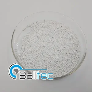
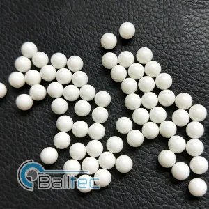
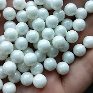
Explore our full line of specialized industrial ceramics, high-density grinding media, and structural dielectric solutions for advanced manufacturing.
Whether you are designing high-voltage HVDC grid compensators, next-generation 800V EV traction inverters, or high-pulsed industrial capacitors in series, our engineering team offers the precision dielectrics, custom array design, and quality assurance your projects demand.