Follow 


Explore our primary engineering range of dielectric ceramic materials, precision milling media, and structural ceramic housings optimized for coupling capacitor manufacturing and high-voltage power applications.
Coupling capacitors serve as indispensable bridge elements in modern electrical power distribution, high-voltage transmission networks, and industrial signal processing architectures. By establishing a low-impedance path for high-frequency carrier signals while presenting an extremely high impedance to power-frequency AC currents (50Hz/60Hz), coupling capacitors enable simultaneous power transmission and telemetry control.
In high-voltage substations, coupling capacitors decouple communications equipment from dangerous power-frequency voltages (up to 765kV or 1100kV AC). They transmit voice, protective relaying signals, tele-control commands, and SCADA data seamlessly over existing power transmission lines, eliminating the need for separate fiber routing in remote utility corridors.
When coupled with an inductive intermediate voltage transformer (IVT) and a compensation reactor, coupling capacitors form CVTs. These devices step down extra-high voltage grid levels to standardized secondary voltages (110V/100V) for revenue metering, relay protection, and real-time phase synchronization across international grids.
Working in tandem with line traps (wave traps) and line matching units (LMU), coupling capacitors prevent high-frequency carrier energy (30 kHz to 500 kHz) from leaking into substation busbars or adjacent line segments, guaranteeing uninterrupted directional protection during line faults.
High-voltage coupling capacitors demand exceptional dielectric integrity, thermal endurance, and mechanical stability under severe environmental stress. Our manufacturing facilities utilize high-purity aluminum foils, micro-calibrated polypropylene dielectric films, and synthetic aromatic insulating oils housed inside high-strength porcelain or composite silicone rubber sheds.
| Parameter / Requirement | Standard Utility Grade | Extra High Voltage (EHV/UHV) | Testing Compliance / Standard |
|---|---|---|---|
| Rated Operating Voltage ($U_n$) | 10 kV – 220 kV | 330 kV – 1100 kV | IEC 60358-1 / IEEE 93 |
| Rated Capacitance Range ($C_n$) | 2000 pF – 20,000 pF | 3000 pF – 50,000 pF | ANSI C83.21 / IEC 60358 |
| Dielectric Loss Tangent ($\tan \delta$) | $\le 0.0015$ (at 20°C, 50/60Hz) | $\le 0.0008$ (Optimized Film Dielectric) | IEC 60358-1 Clause 7.2 |
| Partial Discharge Extinction | $< 10\text{ pC}$ at $1.2 U_n / \sqrt{3}$ | $< 5\text{ pC}$ at $1.5 U_n / \sqrt{3}$ | IEC 60270 / IEC 60358-1 |
| Frequency Carrier Bandwidth | 30 kHz – 500 kHz | 24 kHz – 1000 kHz | CISPR / ITU-T Standards |
| Seismic & Mechanical Load | AG5 (0.3g ground acceleration) | AG7 (0.5g / IEEE 693 High) | IEC 60068-2-57 / IEEE 693 |
| Ambient Temperature Endurance | -40°C to +50°C | -55°C to +55°C (Extreme Climates) | IEC 60068-2-1 / ISO 9001:2015 |
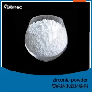
Incorporating ultra-fine Yttria-Stabilized Zirconia (YSZ) and ultra-pure Alumina oxide powders, our insulator housings provide superior dielectric breakdown strength, withstand seismic vibrations, and prevent flashovers under marine salt-fog or heavy industrial pollution (Class IV/V creepage distances).
Equipped with laser-welded stainless steel expansion bellows, the oil volume expansion caused by temperature fluctuations is fully compensated without internal overpressure or vacuum generation, ensuring zero moisture ingress over decades of outdoor service.
China has established itself as the global epicenter for ultra-high voltage (UHV) power gear production. Our integrated manufacturing eco-system combines raw dielectric ceramic powder processing, clean-room foil winding, vacuum oil impregnation, and state-of-the-art high-voltage testing laboratories under one roof.
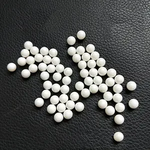
Unlike regional assemblers who source components across multiple continents, our Jiangxi industrial campus conducts everything from sub-micron ceramic grinding (utilizing custom YSZ zirconia media) to metal stamping and high-vacuum oil filling. This vertically integrated control ensures unmatched batch consistency and reduced lead times.
Leveraging massive domestic UHV expansion initiatives, our factories produce tens of thousands of HV coupling units annually. This volume purchasing power allows us to export premium-grade coupling capacitors and voltage dividers to North America, Europe, South America, and Asia at highly competitive total cost of ownership (TCO).
Every single coupling capacitor unit undergoes 100% routine testing prior to export: power frequency withstand voltage test, partial discharge measurement (using Faraday cage isolation), capacitance and $\tan \delta$ testing, and hermetic seal tightness verification. Full type-test reports from KEMA, CESI, or CNAS accredited laboratories are provided upon order confirmation.
Coupling capacitors are deployed across diverse electrical infrastructure settings, from high-altitude solar gathering stations to offshore wind farms and heavy industrial smelting facilities.
Installed at substation entry bays, coupling capacitors enable primary protective relaying (differential protection, phase comparison distance protection) via Power Line Carrier communication. They provide instant fault isolation commands to circuit breakers within milliseconds of line disturbances.
In High-Voltage Direct Current (HVDC) transmission lines connecting giant solar or wind farms to urban load centers, coupling capacitors are combined with high-frequency blocking filters to suppress harmonic noise generated by large IGBT/thyristor converters.
Heavy manufacturing plants—such as steel mills running electric arc furnaces, aluminum smelters, and mining operations—employ heavy-duty capacitor units within passive harmonic filter banks ($5^\text{th}, 7^\text{th}, 11^\text{th}$ harmonics) to stabilize system voltage and improve power factor penalty compliance.
Specialized high-frequency coupling capacitors serve as PD sensors installed directly on gas-insulated switchgear (GIS) or high-voltage power transformers. They pick up ultra-high-frequency (UHF) partial discharge pulses created by insulation defects, enabling predictive maintenance before catastrophic breakdown occurs.
As smart grids evolve toward digitalization, eco-friendly insulating materials, and extreme ambient resilience, coupling capacitor designs are undergoing transformative technological shifts.
Future grid substations rely on optical bus networks. Modern coupling capacitors are integrating fiber-optic sensors directly into the capacitor base, enabling analog high-voltage signals to be converted immediately into process-bus-compatible digital streams per IEC 61850-9-2 standard.
Replacing mineral insulating oils, next-generation coupling capacitors utilize non-toxic, highly biodegradable synthetic ester fluids. These fluids offer higher fire points (>300°C), superior moisture tolerance, and zero soil/water contamination risk in environmentally sensitive regions.
Replacing heavy, brittle traditional porcelain housings, lightweight composite silicone polymer insulators with aluminum flanges are fast becoming the international standard. They provide self-cleaning hydrophobic surfaces and completely eliminate shatter hazards under internal arc pressure.
When issuing RFQs or specifying coupling capacitors for utility tenders, procurement officers and engineering consultants must evaluate these critical parameters to ensure long-term grid compatibility.
Specify the maximum continuous operating voltage ($U_m$), lightning impulse withstand voltage (BIL - e.g., 1050kV BIL for 500kV grids), and short-duration power frequency withstand voltage based on your local network insulation coordination study.
Select the standard capacitance ($C_1$ and $C_2$ for CVTs, or total capacitance $C_n$ for PLC coupling). Ensure the chosen value matches your Power Line Carrier matching unit impedance (typically 50 to 75 ohms) over the intended frequency range (e.g., 40 kHz - 400 kHz).
Determine site-specific conditions: Altitude (if >1000m, insulation correction factors apply), seismic level (IEEE 693 High vs. Moderate), wind speed (up to 50 m/s), and creepage distance ($25\text{ mm/kV}, 31\text{ mm/kV}$, or heavy pollution $43\text{ mm/kV}$).
For Coupling Capacitor Voltage Transformers (CCVT), verify that an integrated damping circuit (passive thermal resistor-inductor network or active electronic damping circuit) is included in the secondary terminal box to suppress sub-harmonic ferroresonance oscillations.
Technical answers for procurement officers, electrical engineers, and substation commissioning contractors.
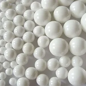
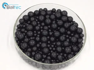
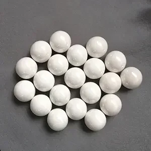
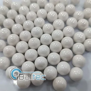
Complementary high-purity ceramic raw materials, high-density grinding spheres, and wear-resistant structural ceramic components manufactured to power-grade standards.