Follow 


Explore our foundational range of ultra-high purity chemical, ceramic, and dielectric refinement products engineered for advanced electronic and industrial applications.
The 10 microfarad (10µF) capacitor occupies a critical nexus point in contemporary electrical engineering. Functioning as the definitive workhorse value for power decoupling, energy storage, high-frequency ripple suppression, and signal conditioning, the demand for 10µF passive components spans virtually every tier of electronic architecture—from ultra-low-power IoT microcontrollers to multi-kilowatt EV traction inverters.
In global electronic manufacturing, achieving a stable 10µF capacitance within increasingly compact package footprints requires sophisticated dielectric material science. Modern electronic hardware designs are moving rapidly toward miniaturization, high energy density, and extreme reliability under severe thermal and mechanical stresses. Consequently, premier 10µF capacitor manufacturers have transitioned from classic liquid-electrolyte constructions to advanced multi-layer ceramic technology (MLCC), solid polymer tantalum, and high-temp aluminum hybrid electrolytes.
Global supply chain dynamics for 10µF capacitors have evolved significantly. While high-volume commercial consumer electronics favor ultra-compact MLCCs (such as 0402 and 0602 package sizes), heavy industrial, aerospace, and automotive sectors prioritize volumetric efficiency, mechanical fracture resistance, and AEC-Q200 qualification compliance. Qualified suppliers must demonstrate end-to-end quality control, from raw ceramic powder synthesis (such as high-purity barium titanate and zirconia dopants) to automated high-speed optical inspection.
The term "10µF Capacitor" encompasses multiple distinct physical topologies. Engineers must navigate trade-offs between physical size, voltage derating, frequency response, and temperature coefficients. The table below presents a comparative analysis of the four primary 10µF capacitor families manufactured by global leaders.
| Topology | Common Case Sizes | Rated Voltage Range | ESR @ 100kHz | DC Bias Effect | Primary Advantage |
|---|---|---|---|---|---|
| Class II MLCC (X7R/X5R) | 0402, 0603, 0805, 1206 | 6.3V – 100V | 1.5 to 10 mΩ | Significant (-20% to -70%) | Ultra-low ESR, high frequency response, SMD footprint |
| Solid Polymer Tantalum | Case A, B, C, P (EIA 0805) | 2.5V – 35V | 15 to 50 mΩ | Zero (0%) | Stable capacitance under DC voltage, no acoustic noise |
| Aluminum Polymer Hybrid | SMD Can (Φ6.3mm – Φ8mm) | 16V – 80V | 20 to 80 mΩ | Zero (0%) | High ripple current tolerance, self-healing dielectric |
| Metallized Polypropylene Film | Radial / Box (10mm - 15mm pitch) | 250V – 900V | 5 to 25 mΩ | Zero (0%) | High voltage tolerance, extreme dV/dt withstand, pulse load |
Utilizing nano-scale Barium Titanate ($BaTiO_3$) ceramic dielectric layers below 0.7 microns, modern 10µF MLCCs achieve phenomenal capacitance density. Specialized X8R and X8L dielectrics extend operating thermal bounds up to +150°C for under-the-hood automotive electronics.
By replacing traditional manganese dioxide ($MnO_2$) with conductive polymer cathode materials, premier suppliers eliminate the catastrophic thermal runaway ignition mode, delivering ultra-reliable 10µF energy storage with flat voltage coefficients.
To counteract board flexure stress in automated surface mount assembly lines, high-reliability 10µF MLCC manufacturers integrate flexible conductive resin termination layers between the copper end electrode and nickel/tin plating.
The manufacturing landscape for high-quality 10µF capacitors is being redefined by four macro-technological catalysts:
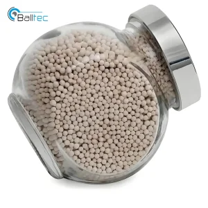
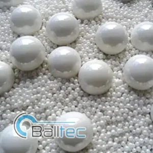
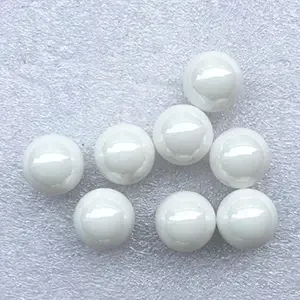
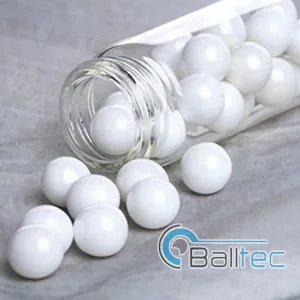
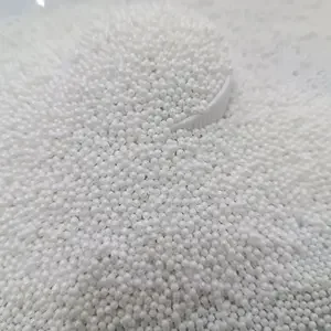
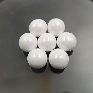
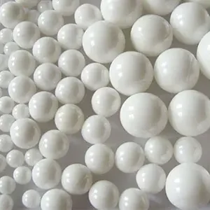
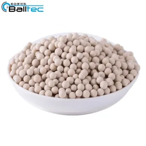
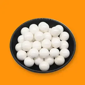
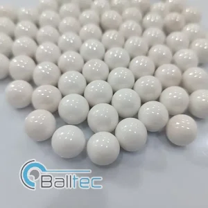
Leading ceramic suppliers are implementing wet-chemical precipitation and ultra-fine dispersion milling using high-density zirconia grinding media. This allows continuous casting of green ceramic dielectric sheets thinner than 500 nanometers, permitting over 800 stacked layers within a single 0603 chip capacitor.
The transition to Gallium Nitride (GaN) and Silicon Carbide (SiC) power semiconductors pushes switching frequencies above 1 MHz to 5 MHz. High-frequency 10µF decoupling capacitors require near-zero Equivalent Series Inductance (ESL) to eliminate ringing and voltage spikes in fast-switching circuits.
Piezoelectric lattice distortion in standard ferroelectric Class II MLCCs generates audible noise (microphonics) in handheld consumer devices and high-end audio gear. Tier-1 manufacturers produce "Low Acoustic Noise" 10µF MLCCs utilizing reverse-geometry terminals or anti-piezoelectric dielectric formulas.
Electric Vehicle powertrains require continuous component operation at ambient temperatures exceeding 150°C. High-reliability 10µF automotive capacitors must pass stringent humidity-load-bias testing (85°C / 85% RH for 1,000 hours) without insulation resistance degradation.
The operational demands placed on a 10µF capacitor vary drastically depending on the deployment environment. Understanding these localized engineering constraints ensures correct component specification.
In Battery Management Systems (BMS) and Autonomous Driving Control Units (ADCU), 10µF capacitors provide low-pass filtering and rail decoupling. Automotive engineers specify 10µF 50V or 100V X7R MLCCs with soft-termination (flex-term) to absorb harsh chassis vibration and thermal shock cycles without short-circuiting.
Baseband processing boards and massive MIMO antenna arrays demand ultra-pure power rails. Low-ESR 10µF polymer tantalum capacitors are deployed directly adjacent to high-current System-on-Chip (SoC) power pins to swallow high-speed transient current loads while maintaining tight voltage tolerances.
Factory automation systems operate in aggressive electromagnetic environments. Metallized film 10µF capacitors rated at 400V to 600V serve as snubbers and DC-link bypass components in variable frequency motor drives, providing high self-healing capabilities against line transients.
As electronic systems push toward higher efficiency, higher switching speeds, and tighter volumetric packaging, the manufacturing roadmap for 10µF capacitors is advancing across three primary engineering frontiers:
Commercial scaling of 10µF capacitance into 0201 (0.6mm x 0.3mm) case sizes. Achieving this milestone requires sub-200nm ceramic grain size powder synthesis and sophisticated dispersion media to prevent pinhole defects in micro-dielectric barriers.
Integration of 10µF thin-film silicon capacitors directly inside IC package substrates or interposers. Silicon deep-trench etching allows ultra-flat profile 10µF devices (<100µm thickness) positioned directly underneath CPU/GPU dies, reducing loop inductance to under 10 picohenries (pH).
Development of anti-ferroelectric and inorganic glass-ceramic dielectrics capable of stable 10µF operation at +200°C to +250°C for deep-well drilling, aerospace turbine sensors, and space exploration power conversion systems.
Optimizing the performance of 10µF capacitors in complex circuits requires rigorous design-for-reliability engineering. Below are three primary integration challenges and supplier-backed solutions:
Challenge: High dielectric constant ($K$) Class II MLCCs experience a decrease in effective capacitance when subjected to a DC operating voltage. A 10µF 6.3V X5R 0402 capacitor operating at 5V DC may lose up to 60-70% of its nominal value, delivering only 3.2µF.
Engineering Solution: Tier 1 suppliers advise upsizing the case size (e.g., from 0402 to 0805) or specifying a higher rated voltage (e.g., 16V or 25V rating). Alternatively, replacing MLCCs with Polymer Tantalum 10µF units guarantees 100% capacitance retention under DC bias.
Challenge: Paralleling a 10µF capacitor with smaller decoupling capacitors (such as 0.1µF or 0.01µF) can create unwanted anti-resonance impedance peaks if trace inductances are improperly laid out.
Engineering Solution: Use multi-terminal Low-ESL capacitors (LW reverse geometry) or select modern low-ESR 10µF MLCCs with optimized self-resonant frequency (SRF) curves to eliminate anti-resonance ringing across broadband power planes.
Challenge: High AC ripple current in power supplies causes internal $I^2R$ self-heating, accelerating dielectric breakdown and reducing capacitor lifespan.
Engineering Solution: Implement high-purity aluminum polymer hybrid or high-temperature MLCC series. Suppliers provide complete S-parameter data and SPICE thermal simulation models to verify junction temperatures under max load conditions.
Explore our second selection of precision manufacturing consumables, fine grinding media, and structural ceramic powders supporting modern electronic component fabrication.
Engineering and procurement teams regularly encounter complex qualification criteria when sourcing 10µF capacitors. Below are definitive, expert-vetted technical responses.