Follow 


Direct factory sourcing options for advanced industrial applications, ultra-fine material processing, and precision component integration.

Understanding the role of the 0.01 µF (10 nF / 103 EIA Code) capacitance value in modern electrical engineering, circuit decoupling, high-frequency noise mitigation, and signal conditioning.
In the hierarchy of passive electronic components, the 0.01 µF capacitor (equivalent to 10 nanofarads [nF] or 10,000 picofarads [pF]) represents one of the most critical foundational building blocks in printed circuit board (PCB) design. Found across consumer electronics, industrial automation, automotive control units, telecommunication base stations, and power supply modules, this capacitance value is strategically positioned at the threshold between high-frequency RF suppression and low-frequency ripple filtering.
When evaluated through the lens of semiconductor power distribution networks (PDN), a 0.01 µF capacitor acts as a localized energy reservoir. It bridges the transient impedance gap between smaller high-frequency decoupling capacitors (e.g., 1000 pF / 1 nF) and bulk storage capacitors (e.g., 1 µF to 10 µF). By maintaining a minimal Equivalent Series Resistance (ESR) and Equivalent Series Inductance (ESL), a properly specified 0.01 µF capacitor suppresses voltage sag, eliminates electromagnetic interference (EMI), and prevents high-frequency switching noise from destabilizing sensitive microcontrollers, digital signal processors (DSPs), and Field-Programmable Gate Arrays (FPGAs).
The practical performance of a wholesale 0.01 µF capacitor is governed by its self-resonant frequency ($f_0$). Below $f_0$, the component behaves strictly as a capacitive element with impedance decreasing as frequency increases ($Z = \frac{1}{2\pi f C}$). At $f_0$, the capacitive reactance and inductive reactance cancel each other out, achieving minimum impedance equal to the ESR. Above $f_0$, parasitic package inductance dominates, causing impedance to rise and turning the component inductive.
In surface-mount MLCC configurations (0402/0603 footprints), a 0.01 µF capacitor typically exhibits an SRF ranging between 15 MHz and 50 MHz, making it ideal for suppressing clock harmonics and switching transients.
Depending on dielectric selection (Class I C0G/NP0 vs Class II X7R/X5R), capacitance deviation across operating thermal ranges ($-55^\circ\text{C}$ to $+125^\circ\text{C}$) can be constrained to $\pm 30\text{ ppm/}^\circ\text{C}$ or $\pm 15\%$.
Advanced high-voltage 0.01 µF capacitors utilize optimized Barium Titanate ($\text{BaTiO}_3$) crystalline structures to minimize capacitance drop under DC bias conditions.
Selecting the ideal dielectric substrate for 0.01 µF capacitors: A comparative analysis of MLCC Class I, Class II, Film, and Ceramic Disc structures.
When evaluating a wholesale 0.01 Uf capacitor supplier, procurement teams and principal hardware engineers must scrutinize dielectric characteristics. The physical dielectric determines not only thermal stability and lifetime reliability, but also mechanical stress resistance, breakdown voltage safety margins, and microphonic susceptibility.
| Dielectric Type | EIA Code / Standard | Temp. Coefficient Range | Dissipation Factor ($\tan\delta$) | Key Application Strengths | Target Industrial Market |
|---|---|---|---|---|---|
| C0G / NP0 Ceramic | Class I Ultra-Stable | $-55^\circ\text{C}$ to $+125^\circ\text{C}$ ($\pm 30\text{ppm/}^\circ\text{C}$) | < 0.1% max | Zero DC bias capacitance drop, zero microphonics, linear thermal response. | Precision RF Filters, Resonant Circuits, Medical Instrumentation. |
| X7R Multilayer Ceramic | Class II High-K | $-55^\circ\text{C}$ to $+125^\circ\text{C}$ ($\pm 15\%$) | < 2.5% max | High volumetric efficiency, low cost, excellent IC power decoupling. | Automotive ECU, Industrial Automation, Telecommunications. |
| X5R Multilayer Ceramic | Class II High-K | $-55^\circ\text{C}$ to $+85^\circ\text{C}$ ($\pm 15\%$) | < 3.0% max | Cost-optimized for commercial temperature range devices. | Consumer Smart Devices, Compute Peripherals, IoT Nodes. |
| Metallized Polypropylene Film | MKP / CBB | $-40^\circ\text{C}$ to $+105^\circ\text{C}$ ($\pm 5\%$) | < 0.05% max | Self-healing capability, extremely high dv/dt pulse handling, high voltage ratings. | EV Inverters, Switching Power Supplies (SMPS), Snubber Networks. |
| High-Voltage Ceramic Disc | Class II / III (Y5P, Z5U) | $-30^\circ\text{C}$ to $+85^\circ\text{C}$ ($+22\% / -56\%$) | < 2.5% max | High creepage distances, safety agency rated (X1/Y2 options), surge protection. | AC Line Filtering, Surge Suppressors, Power Grid Controls. |
Strategic analysis of global supply chains, bulk procurement lead times, vendor risk mitigation, and cost-volume scaling for 0.01 µF passive components.
The global demand for 0.01 µF capacitors exceeds hundreds of billions of units annually. Procurement managers must evaluate suppliers based on raw material vertical integration—specifically raw Barium Titanate ($\text{BaTiO}_3$) synthesis, inner electrode nickel paste refining, and automated high-speed taping/reeling facilities.
To hedge against geopolitical supply disruptions and semiconductor cycle swings, leading OEMs mandate Vendor-Managed Inventory (VMI) arrangements. Qualified wholesale suppliers provide safety buffers near major manufacturing hubs, ensuring 48-hour delivery windows.
Unit pricing for wholesale 0.01 µF MLCCs is highly sensitive to tape-and-reel quantities (e.g., 4,000 pcs vs 10,000 pcs per reel). Beyond component piece price, TCO accounts for line-stoppage risks, pick-and-place rejection rates (PPM level), and solderability shelf life.
How wholesale 0.01 µF capacitors power mission-critical hardware across automotive electronics, 5G telecom, industrial automation, and energy conversion systems.
Electric Vehicle (EV) battery management systems (BMS), traction inverters, and Advanced Driver Assistance Systems (ADAS) require component operation up to $+125^\circ\text{C}$ or $+150^\circ\text{C}$. In these systems, 0.01 µF AEC-Q200 MLCCs with open-mode or flexible termination (soft termination) prevent board-flex crack failures caused by thermal shock and vibration, safeguarding against short-circuit fire hazards.
High-speed wireless communication nodes demand ultra-clean DC voltage rails. Placing ultra-low ESR 0.01 µF C0G capacitors in parallel with 0.1 µF and 100 pF components creates a broadband decoupling matrix. This suppresses phase noise in Phase-Locked Loops (PLLs) and Power Amplifiers (PAs) operating in sub-6 GHz and millimeter-wave (mmWave) frequency spectrums.
In noisy industrial environments dominated by heavy motor switching transients, 0.01 µF ceramic disc and film capacitors are deployed as dV/dt snubbers across IGBT and SiC MOSFET switches. They absorb inductive voltage spikes, protect power semiconductors from breakdown, and ensure compliance with global EMC emission standards (CISPR 32 / EN 55032).
Patient monitoring systems, ultrasound beamformers, and implantable neurostimulators require ultra-compact components with near-zero leakage current ($I_{\text{leak}}$). High-reliability 0.01 µF MLCCs processed via specialized HIP (Hot Isostatic Pressing) sintering eliminate internal voids, guaranteeing mean-time-between-failures (MTBF) exceeding tens of millions of operating hours.
Where dielectric engineering is heading: Ultra-miniaturization, Wide Bandgap (GaN/SiC) integration, and ultra-high thermal tolerance.
Transitioning 0.01 µF MLCC footprints down to sub-millimeter package sizes, enabling embedding directly within IC substrate interposers.
Synthesis of advanced Class I dielectric formulations capable of maintaining capacitance stability near jet engine sensors and deep-well drilling tools.
LW Reverse Terminations (e.g., 0306 vs 0603) reducing ESL by over 60%, pushing self-resonant frequencies beyond 100 MHz.
Ultra-low loss snubber capacitors designed for fast switching speeds (>500 kHz) and extreme high voltage gradient environments.
100% RoHS/REACH compliant lead-free glass frits and nickel-tin terminations optimized for automated lead-free reflow profiles.
Strict zero-defect quality protocols implemented by premier wholesale 0.01 Uf capacitor suppliers to guarantee batch-to-batch consistency.
Industrial component sourcing demands rigorous quality verification beyond basic spot testing. Leading manufacturers employ automated 100% optical and electrical testing alongside statistical process control (SPC) during dielectric tape casting, screen printing, and co-firing.
Automotive-grade 0.01 µF components undergo severe environmental validation, including 1,000 cycles of thermal shock ($-55^\circ\text{C}$ to $+125^\circ\text{C}$), 1,000 hours of Biased Humidity Testing ($85^\circ\text{C} / 85\%\text{ RH}$), and board-flexure testing up to 2 mm minimum bend depth.
Precision sectioning, scanning electron microscopy (SEM), and acoustic microscopy are utilized to inspect internal ceramic layers for micro-cracks, electrode delamination, void formation, or dielectric layer thickness variations.
Plating adhesion of the nickel barrier layer and matte-tin outer layer is tested in accordance with MIL-STD-202 Method 208 to eliminate dewetting, tombstoning, or terminal leaching during surface-mount reflow assembly.
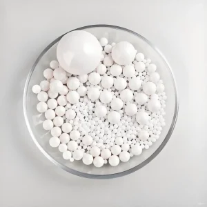
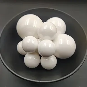
Complete product catalog selections for high-purity processing, catalyst support, and ultra-fine dispersion media.

A framework for procurement executives to audit potential 0.01 µF capacitor suppliers, minimize risk, and secure direct factory pricing.
Verify factory monthly throughput, automated casting line capacity, and sintering furnace technology. High-volume suppliers should maintain an annual production capacity exceeding 5 billion passive components to guarantee scalable pricing.
Ensure vendor compliance with ISO 9001 (Quality Management), ISO 14001 (Environmental Management), and IATF 16949 (Automotive Quality Standard). Demand batch traceability from raw material powder lots to final tape-and-reel shipment.
Evaluate Minimum Order Quantities (MOQ), reel packaging options, standard lead times (e.g., 4 to 8 weeks), and shipping terms (FOB, CIF, DDP). Strategic buyers negotiate buffer stock commitments to eliminate production downtime.
Direct, engineer-verified answers to common technical queries and procurement specifications for 0.01 µF capacitors.