Follow 


Factory-direct high-purity ceramic media, engineered powders, and dielectric materials supporting global MLCC and capacitor manufacturing lines.
The 0.1 µF (100nF) capacitor represents the universal benchmark standard in digital circuit decoupling, noise suppression, and power distribution network (PDN) stabilization across modern electronics manufacturing.
In modern electronic architecture, the 0.1 uF capacitor (100,000 pF or 100nF) is the primary IC power pin bypass element. By providing a local energy reservoir, it buffers transient switching current spikes generated by high-speed microprocessors, FPGAs, and ASICs, preventing power rail ripple voltage collapse.
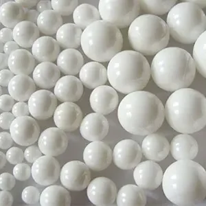
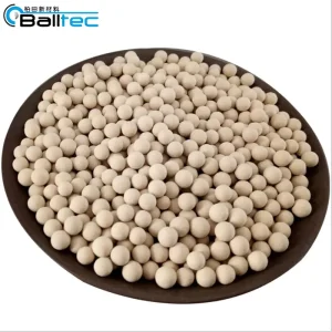
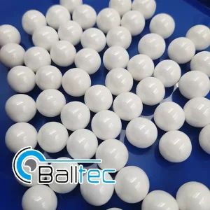
Utilizing high-purity barium titanate ($BaTiO_3$) ceramic dielectric formulations—processed with ultra-fine zirconia and alumina grinding media—our 0.1 µF capacitors achieve exceptional volumetric efficiency, low Equivalent Series Resistance (ESR), and minimal Equivalent Series Inductance (ESL) across megahertz and gigahertz frequency bands.
As a tier-one supplier and exporter, we support automated surface-mount (SMT) tape-and-reel packaging standardizations. Our global supply chain guarantees batch-to-batch capacitance uniformity, zero-defect solderability, and strict adherence to international commercial procurement cycles.
Selecting the optimal 0.1 uF capacitor requires precise alignment between dielectric classification, voltage bias breakdown ratings, thermal coefficients, and package geometry.
| Dielectric Material | EIA Class | Temperature Range | Capacitance Drift (ΔC) | ESR & ESL Profile | Typical Applications |
|---|---|---|---|---|---|
| C0G / NP0 (Ceramic) | Class I | -55°C to +125°C | ±30 ppm/°C (0.05%) | Ultra-Low ESR / Min ESL | Precision RF Filters, High-Q Circuits, Timing Networks |
| X7R (Ceramic) | Class II | -55°C to +125°C | ±15% | Low ESR / Optimized SMT | Industrial IC Decoupling, Automotive ECU, Bypass |
| X5R (Ceramic) | Class II | -55°C to +85°C | ±15% | Low ESR / High Volumetric | Consumer Electronics, Mobile Devices, IoT Modules |
| Metalized Polyester (Film) | Film Dielectric | -40°C to +105°C | ±5% / ±10% | Self-Healing / Low Distortion | Audio Signal Paths, Pulse Circuits, AC Mains Filtering |
| X8R / High Temp Ceramic | Class II (Extreme) | -55°C to +150°C | ±15% | Thermally Stable ESR | Under-the-Hood Automotive, Downhole Drilling, Avionics |
In Class II MLCCs (such as X7R and X5R 0.1 uF capacitors), applying a DC operating voltage reduces effective capacitance. Our advanced micro-grain ceramic dielectric engineering reduces DC bias degradation by up to 35% compared to standard commercial MLCCs, retaining true 100nF capacitance at nominal operating voltages.
At frequencies below the SRF, a 0.1 uF capacitor behaves as a pure capacitive reactance. Above its SRF (typically between 10 MHz to 50 MHz depending on package sizes like 0402, 0603, or 0805), lead inductance dominates. Our low-ESL geometries push the SRF higher, extending noise suppression into GHz bands.
From EV inverter gate drivers to smart grid automation, our wholesale 0.1 µF capacitors provide proven operational stability across challenging environments.
Deployed in Battery Management Systems (BMS), Traction Inverters, and Advanced Driver Assistance Systems (ADAS). Automotive-grade 0.1 uF X7R/X8R capacitors withstand intense mechanical vibration, thermal cycling (-55°C to +150°C), and flexural board stress via soft-termination technology.
Used extensively in 5G Small Cells, Base Station Active Antenna Units (AAU), and high-speed routers. Low-ESR 0.1 uF capacitors filter high-frequency phase noise, ensuring signal clarity across sub-6 GHz and millimeter-wave (mmWave) spectrums.
Integrated into Programmable Logic Controllers (PLCs), Variable Frequency Drives (VFDs), and smart meters. High-voltage 0.1 uF film and ceramic capacitors provide snubber circuit protection, transient voltage surge absorption, and EMI input filtering.
Our zero-defect quality policy integrates raw material powder synthesis, precision sintering, ultrasonic inspection, and 100% automated optical testing.
As silicon carbide (SiC) and gallium nitride (GaN) semiconductors shrink power electronics footprints, our capacitor roadmap focuses on high-frequency, high-temperature, and ultra-compact dielectrics.
By refining ceramic powder grinding techniques down to nano-scale grain sizes (< 100 nm), our next-generation 0.1 uF MLCCs achieve stable 100nF capacitance in 0201 and 01005 surface-mount footprints without sacrificing dielectric breakdown margin.
GaN and SiC power switches operate at multi-megahertz frequencies with steep $dV/dt$ voltage gradients. We are pioneering ultra-low inductance reverse-geometry MLCCs (LW1812/0508) and high-temperature Class I C0G dielectrics capable of continuous operation at 175°C.
To eliminate stray PCB trace inductance, our engineering teams collaborate with global substrate manufacturers to produce ultra-thin (down to 150 µm thickness) embedded 0.1 uF capacitors designed for direct integration within IC package substrates.
Expert technical answers addressing selection criteria, performance trade-offs, and bulk export procurement of 0.1 µF capacitors.
Explore our full ecosystem of high-strength industrial ceramic spheres, molecular sieves, and precision electronic materials.